
Higher volumetric heat generation is anticipated while miniaturizing electronics
in engineering applications. Recent days, this value of heat flux released from electronics
is as much as 1 MW/m^2 (100 W/cm^2).
For faultless working of the electronics, the generated heat has to be dissipated quickly.
This is to ensure the electronics are maintained below a set point temperature during operation,
usually the junction temperature of the transistors (SPT < ~ 90 to 120 ° C).
By changing phase from solid to liquid (melting) or from one solid structure to another,
Phase Change Materials (PCM) absorb large latent heat at a constant temperature. So, heat sinks connected
to electronics suitably and using PCMs such as high carbon paraffin are used in the temperature
control of portable electronic devices. In its simplest form, one can imagine such heat sinks as a
large box of PCM attached to the electronic modules.
However, the low conductivity of the PCM is a hindrance by the creation of hot spots. This is
overcome by a Composite Heat Sink (CHS), comprising a judicious distribution of high thermal
conductivity Base Material (BM) along with the PCM. The thermal design of such a CHS, constructed
using a vertical array of ‘fins’ or Elemental CHS (ECHS) of similar shape and size, made of PCM and BM,
for its performance improvement has also been studied in detail by many researchers in the recent
decade [1]. One such simple design is shown in Figure 1 below.

Figure 1
For a CHS constructed with the design in Fig. 1, operating under a given SPT, under-usage of the
latent heat of the PCM because of incomplete melting is a more critical CHS issue than the complete
melting of PCM before the CHS reaches the SPT. The former results in a poorly performing CHS while the
latter merely reduces the CHS potency for heat transfer enhancement. This is because after complete
melting, the PCM continues to receive heat as sensible heat, instead of as latent heat. This
maximization of the operation of CHS can be resolved [2]
For a chosen PCM quantity, a “critical upper-bound dimension” (d_c and B_c) for the
ECHS, as shown in Figure 2b, can be determined by analysis. Constructing a CHS (shown in Figure 2a)
with a finite number of ECHS (shown in Figure 2b) made of the critical dimensions (d = d_c and B = B_c)
ensure complete melting of all of the PCM exactly when the SPT is reached. This design gives an
increased time of operation for the CHS.
In a CHS design of Figure 1, exhausting all of the PCM latent heat storage before
SPT is reached, should result in maximum time of operation of the CHS.
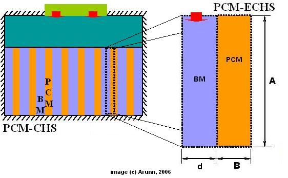
Figure 2
The above CHS idea is not far-fetched. See for instance
[
ESLI Products: PCM Heat sinks ]. This product, shown below, is a typical PCM based CHS that
uses light weight brush like metal fibers as interconnecting media pervading the PCM matrix,
different from the simple parallel ECHS arrangement shown in Figure 1.
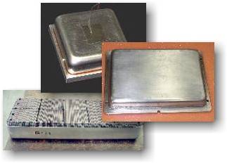
According to the ESLI website,
ESLI’s paraffin based heat sinks can be designed to operate at or near 5, 18, 28,
37, 44, 55, or 61 ° C. Non-paraffin based designs are also available for cryogenic or high temperature applications. ESLI’s PCM composite heat sinks have been space flight tested on the Space Shuttle (STS-95) aboard the CRYOTSU experiment module, and will fly aboard NASA’s Vegetation Canopy LIDAR experiment in 2000.
For an illustration of the applicability of the CHS explained in Fig. 1 and 2, consider a
cooling application that requires a thermal dissipation of 62.5 W from its electronics that are
to be maintained below 90 ° C. For a typical CHS surface area of 5cm x 5cm, the heat
flux received from the heat dissipation of the electronics would be q” = 25 kW/m^2.
By choosing a CHS with D = 5 cm (left to right length, in Figure 1) and height A = 5 cm (see Fig. 2a),
the number of critical dimensioned ECHS (Fig. 2b) made of 50 percent of PCM that should
fill the CHS (Fig. 2a) can be calculated from analysis [2]. This would be
d_c = B_c = 0.004 m (see Fig. 2b). The number of such ECHS (Fig. 2) that would fill the CHS
in Fig. 1 would then be equal to four. For such a design the CHS could operate successfully for about
453 seconds. After this period, the CHS has to be cooled to release all of the stored
energy in the PCM, before charging it again.
A CHS design not dissimilar to the one in in Figure 1 and 2, is required for cooling the
on-board electronics in the space vehicles launched
by ISRO, the Indian Space Research Organization.
Such a CHS has to operate successfully by receiving maximum energy and not allowing the
electronics to reach SPT (~ 90 ° C) for about 20 to 30 minutes – flight time of a pay-load
carrying rocket one way into space.
Using such a design for space-bound electronics cooling applications has been successful.
A product developed by NASA
to cool on-board space batteries in rockets,
utilizes carbon fibers as the metal BM, a variant from the above CHS design of Figure 1 and 2.
Major Reference Discussed
Akhilesh, R., Narasimhan, A. and Balaji, C., (2005), “Method to Improve Geometry for Heat Transfer Enhancement in PCM Composite Heat Sinks” Int. J. Heat and Mass Transfer, 48, 2759-2770. [DOI 10.1016/j.ijheatmasstransfer.2005.01.032]
